Configure Keys
Supports configuring GPIO pins for keys through AT commands.
Currently, the GPIO pins corresponding to the three buttons in the kit are as follows:
Button A - GPIO 18
Button B - GPIO 19
Button C - GPIO 5
GPIO
Currently, there are a total of 8 configurable GPIO pins:
5, 18, 19, 21, 25, 33, 36, 39Each key must correspond to a separate GPIO pin.
Configure talk key:
Example: Define talk key as GPIO 27
at+keys=talk,<GPIO> // at+keys=talk,27
Switch recording mode
Example: press the recording button to enter recording, release the button to end recording
at+command=record,pressExample: click the recording button to enter the recording, and it will automatically end after the recording is completed
at+command=record,clickExample: click the recording button to enter continuous conversation mode
at+command=record,continuous
Configure enter dialogue mode key:
Example: Define enter dialogue mode key as GPIO 29 and GPIO 30
at+keys=dialogue,<GPIO>;<GPIO> // at+keys=dialogue,29;30
Configure role:
If not configured, the default role ID is 1.
Example: Define GPIO 22 as the key for role 1
at+keys=role_idx,<index>,<GPIO> // at+keys=role_idx,1,22Example: Remove key definition for role 1
at+keys=role_idx,<index>,<GPIO> // at+keys=role_idx,1,0
Configure switch role key:
Example: Configure GPIO 27 to switch to the previous role
at+keys=role_prev,<GPIO> // at+keys=role_prev,27Example: Configure GPIO 28 to switch to the next role
at+keys=role_next,<GPIO> // at+keys=role_next,28
Specific Steps
Connect the interface expansion board to a PC using the provided Type C data cable.
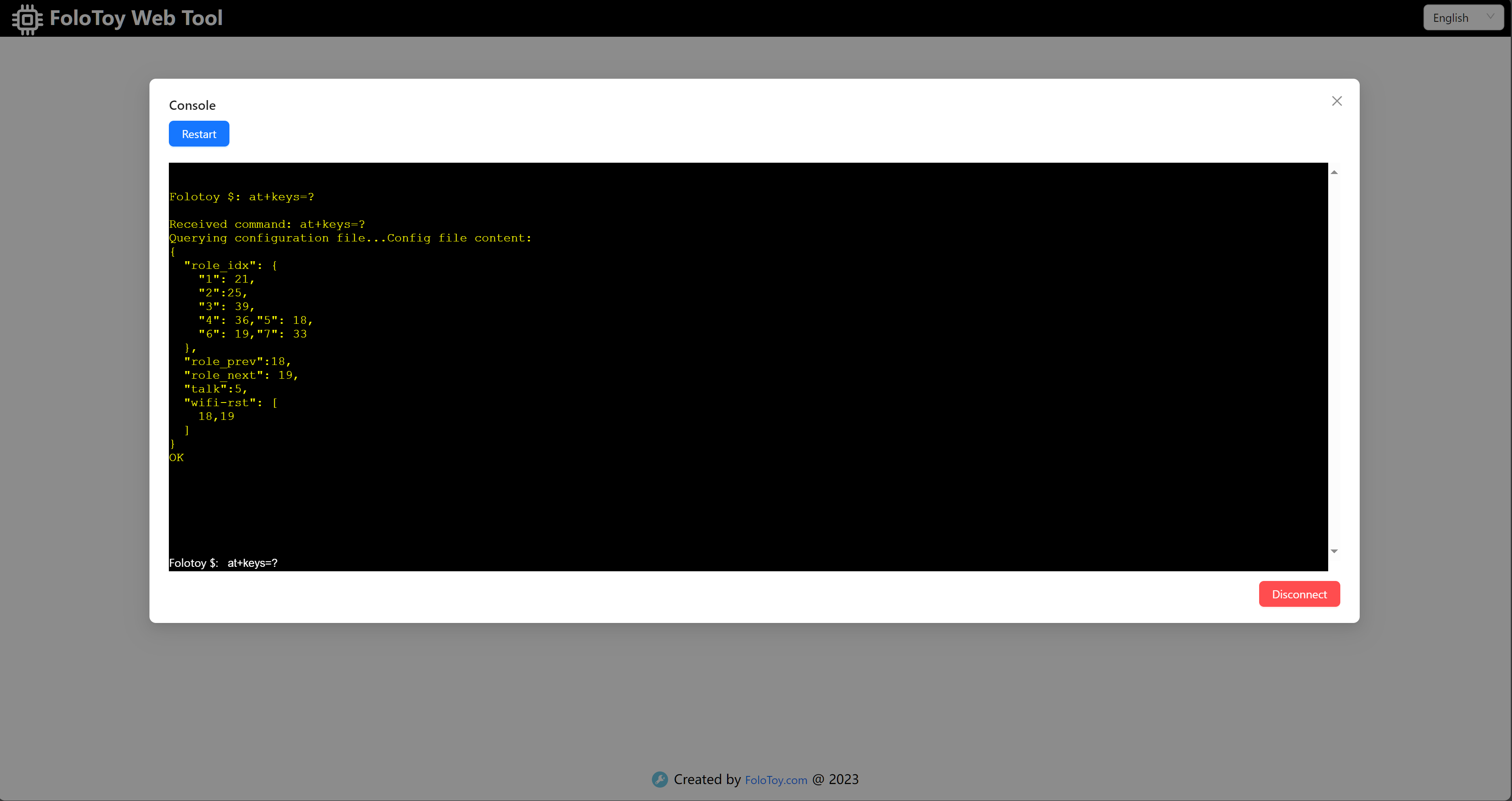
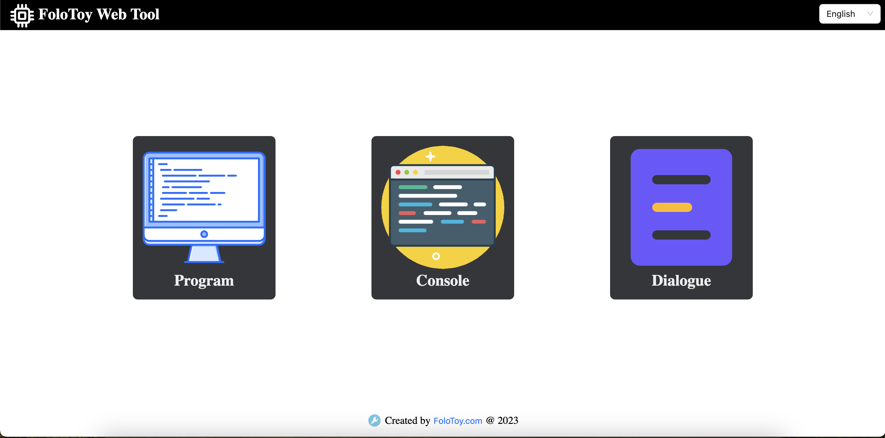
Open the web tool and navigate to the logs.
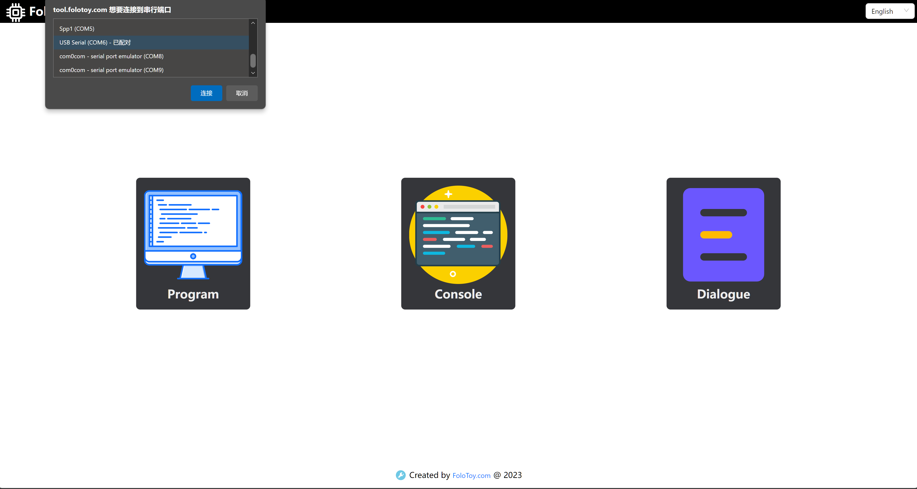
Select the serial port for the kit and click "Connect."
Enter the AT command in the pop-up log box.